 In the last posts we emphasized the basic system engineering concept of a clear distinction between
- system components – or items in the wider sense – and
- system functions.
Today’s video post shows a way to support this concept by modular RAMS blocks in a basic risk assessment example: the analysis of an emergency power system. An auxiliary power bus has to provide the electricity used for internal operations in a nuclear power station, like cooling pumps, control system or manipulating the nuclear fuel elements. So power failure on this Aux bus is surely a safety-critical event or hazard.
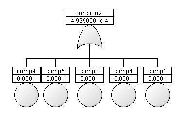
Using a modular, graphical system model allows to easily evaluate the effects of a local component failure – which might remind you to the common FMEA procedure – and automatically determine all possible root causes of a system function failure. But the risk assessment procedure is supported also quantitatively, by assigning
- by assigning individual MTBF values and failure rates on component level and
- defining an upper limit of the “to-be”-failure rate on function level.
The fault tree for each undesired event of a failed function – the hazard in this risk assessment example – is derived automatically. So we can easily check if the failure rate requirements are met by anticipated architectural design of the power supply system and the quality of the component.
Although this system is comparatively simple and has two fully separated and independent branches, the example shows the benefit of the option to quickly change parameters of components or functions and to – in a wider scope – support also the requirements engineering process. In a later contribution we will analyze also seemingly independent supply branches, but which have hidden dependencies in form of common components or even common cause of failure. (Please note that the selected failure rate values just serve as placeholders here.)
In post [006] we will introduce the idea of availability modeling and the appropriate layer in the SmartRAMS library that allows to quickly determine the availability of a system.

 The Idea