 In post [003] we referred to “each directly or indirectly required componen“, when talking about determination of the system function’s failure rate. But which components are required? – Well, basically all these individual items or combinations of items whose local failure will affect the considered function in a way that it does not work any longer.
In other words, we have to find out those components that are crucial for the functionality. A common way of doing that is a so-called root-cause investigation, assuming the individual function has failed.
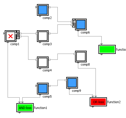
One aspect of this post’s video is the demonstration, how these root-causes can easily be derived from the functional system model, using a kind of automatic backward reasoning. For each detected root-cause – be it a single fault, double fault or even higher order fault – the graphic of the connected SmartRAMS-blocks displays the affected system parts for each particular scenario.
Root cause analysis is often performed during system operation – i.e. late in the product life cycle – during diagnosis or troubleshooting. However, its reasoning and findings are very related to the top-down investigation in the context of a Fault Tree Analysis FTA, usually performed very early in product development.
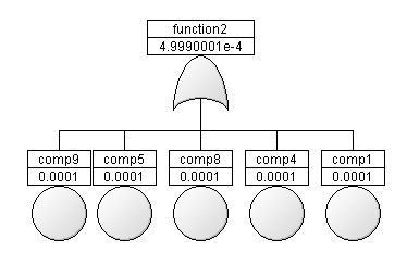
Risk analysis by FTA has the goal to check if the safety and reliability requirements are met by the anticipated architecture. The system model composed from the simple Boolean library items supports also this purpose. We can automatically derive the Fault Trees and – as a side effect – compute the function failure rates from the component’s lambda-values. This is the other aspect shown in the video:
In post [005] we are going to demonstrate these features using a emergency power system as a simple risk assessment example.

 The Idea