Category Archives: Product Development

Availability Requirements Engineering Video

[008] Using a System Model for Iterative Availability Management

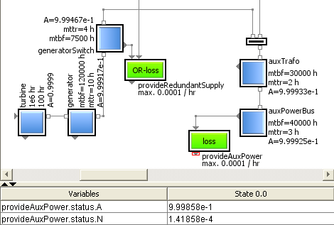
Using a System Model For Iterative Availability Management, Power Supply System ExampleThe description of the last post [007] showed, how we added related quantities and arithmetics to compute availability and non-availability for individual items. This extension made them smarter and also added some “decoration” to display the parameter values.

Today’s video post guides us from item level back up to system level. At the end of the day, it is the availability of a system – or better: of certain system functions – that we are interested in.


Simply by using the amended versions of the original item classes allowed it to extend the benefit of the existing system model – here in the example of the power supply system – without actually having to touch and modify it in any way. The topology remains the same as already known and graphically specified before.

The idea is, that the individual topological context of an individual item not only determines its functionality, but also the computation of the availability of a service that this item shall provide. That means, not only its own “standalone” properties of the relevant parameters – like MTBF and MTTR as shown in post [007] – determine the service availability, but also its individual supplies have to be taken into account.

According to the local dependencies of the individual item the behavior description of its unique category automatically provides the correct arithmetics to compute this availability value. That makes it very easy to compute the availability of a system, since the computation equation is assembled automatically, just by graphically connecting the various outputs and inputs of the used items – independent if they represent real hardware components, process steps or e.g. logistical activities.

Having direct and interactive access to all relevant parameters allows to easily modify values of Mean Time Between Failures MTBF or Mean Time To Repair MTTR of any item. Just by doing a system simulation it immediately becomes clear, if these modifications help to come closer to the target number – like five nines – or also the MTBF or MTTR requirements of other items have to be tightened.

So using a graphical hierarchical system model to iteratively find out optimal target values for the items or item categories – including the feature to save and load scenarios – adds a great flexibility to the process of availability management or specification. In a later post we plan to support this process even more by considering also criteria like cost or time to get a better idea of the performance of designated assembly architectures.

In this example we assumed that the parameters MTBF and MTTR – as some of the main drivers of item availability – were given. But they are just some statistical values and depend on other properties as well. How the target function availability of a system really is affected in case a certain item is down, will probably be the topic of post [009].

For the time being, feel free to get in contact with us. Get in contact ...

Availability Reliability Requirements Engineering

[007] Amending Item Models by MTTR and Availability Computation

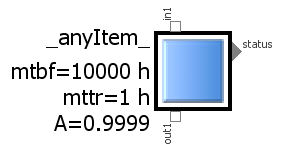
Item model with parameters MTBF and MTTR and associated item Availability, displyed as simple block iconIn this post we’re going to amend the existing library blocks by the quantities and arithmetics introduced in post [006] and see how this can facilitate the computation of the availability of a system.

What we need in the first step are the required variable and parameter slots, assigned to each individual item. For the time being we assume that the Mean Time To Repair MTTR is given as a known parameter for each item with the default unit of hours.


In the Modelica modeling language, parameters are quantities whose value has to be assigned prior to a simulation run, i.e. they will not be calculated. In that aspect the parameter type differs from normal variables. We plan to consider also other ways to determine and represent the MTTR and will describe this in future posts.

Cartoon, Maintenance and Lubrication, Improving Mean Time Between Failures MTBFSince the Mean Time Between Failures MTBF has been introduced in a similar parametric way in the default item, the local availability A of this particular item may immediately be calculated according to the arithmetics in post [006]. So if the pre-assigned parameter values of MTBF is 10000 hours and the Mean Time To Repair is 1 hour, this results in a local item availability of 0.9999 or 99.99%. In case we want to achiev 99.999% i.e. five nines, we would have to modify e.g. MTTR to 0.1 hour – i.e. speed up the repair action – or increase MTBF to 100000 hours – i.e. get higher-quality parts. Since such modifications can be done interactively “on the fly”, this might help the system engineer to specify the quality requirements.

We may specify in the item graphics, that these parameter values shall be displayed besides the visual icon, along with the individual name (see intro figure).

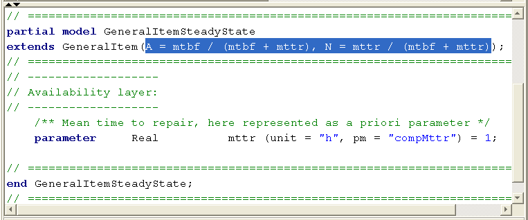
As the modeling approach follows an object-oriented concept, all item models are derived from one general item class and we need to do these declarations only at a single spot in the library. The next figure shows how this new functionality can be implemented very quickly in a few lines of code in the internal modeling language. Its only a reference to the GeneralItem master model, the equations for A and N and the declaration of the mttr parameter in a one-liner:

Amending the base class by parameters and arithmetics to compute the Availability and Non-Availability of an item

Before we proceed, it’s important to understand what we really have achieved now. We have just added the parameter MTTR to the master item description in the library. Such an item might represent various things like

  • a certain technical hardware unit within a machine,
  • a process step within a bigger procedure,
  • an adminstrative item within an organisation
  • or any other kind of element in a bigger context.

Together with the already existing parameter MTBF this allowed us to compute the also newly introduced availability quantity A. However, this item availability value is rather a theoretical value, describing a statistical value of this “box” in a standalone view, assuming that it is properly supplied.

In a real system, such an item almost never exists isolated. Instead, it will be connected to and interacting with its neighbors in a more or less complex environment. So in order to compute the actual service availability at the output of this box, we have to consider also the individual supply situation at its input. This will be the topic of post [008], then allowing us to efficiently compute the service availability of the power supply system from post [005]. And the good message is: this is possible without having to touch the overall system model!

Thanks for sharing this article!

Architecture RAMS Reliability Requirements Engineering Safety Video

[005] Risk Assessment Example: An Emergency Power System

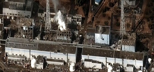
Potential hazard in case of Aux power failure in a nuclear power station, Fukushima I by Digital Globe BIn the last posts we emphasized the basic system engineering concept of a clear distinction between

  • system components – or items in the wider sense – and
  • system functions.

Today’s video post shows a way to support this concept by modular RAMS blocks in a basic risk assessment example: the analysis of an emergency power system. An auxiliary power bus has to provide the electricity used for internal operations in a nuclear power station, like cooling pumps, control system or manipulating the nuclear fuel elements. So power failure on this Aux bus is surely a safety-critical event or hazard.


Using a modular, graphical system model allows to easily evaluate the effects of a local component failure – which might remind you to the common FMEA procedure – and automatically determine all possible root causes of a system function failure. But the  risk assessment procedure is supported also quantitatively, by assigning

  • by assigning individual MTBF values and failure rates on component level and
  • defining an upper limit of the “to-be”-failure rate on function level.

The fault tree for each undesired event of a failed function – the hazard in this risk assessment example – is derived automatically. So we can easily check if the failure rate requirements are met by anticipated architectural design of the power supply system and the quality of the component.

Although this system is comparatively simple and has two fully separated and independent branches, the example shows the benefit of the option to quickly change parameters of components or functions and to – in a wider scope – support also the requirements engineering process. In a later contribution we will analyze also seemingly independent supply branches, but which have hidden dependencies in form of common components or even common cause of failure. (Please note that the selected failure rate values just serve as placeholders here.)


In post [006] we will introduce the idea of availability modeling and the appropriate layer in the SmartRAMS library that allows to quickly determine the availability of a system.


Architecture Product Development RAMS Reliability Safety Video

[004] From Root Cause Investigation to Fault Tree Analysis

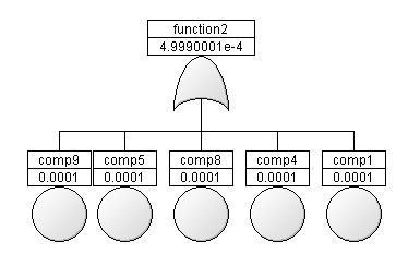
Example Fault Tree Analysis FTA, generated automatically from a component modelIn post [003] we referred to “each directly or indirectly required componen“, when talking about determination of the system function’s failure rate. But which components are required? – Well, basically all these individual items or combinations of items whose local failure will affect the considered function in a way that it does not work any longer.


In other words, we have to find out those components that are crucial for the functionality. A common way of doing that is a so-called root-cause investigation, assuming the individual function has failed.

One aspect of this post’s video is the demonstration, how these root-causes can easily be derived from the functional system model, using a kind of automatic backward reasoning. For each detected root-cause – be it a single fault, double fault or even higher order fault – the graphic of the connected SmartRAMS-blocks displays the affected system parts for each particular scenario.

Root cause analysis is often performed during system operation – i.e. late in the product life cycle – during diagnosis or troubleshooting. However, its reasoning and findings are very related to the top-down investigation in the context of a Fault Tree Analysis FTA, usually performed very early in product development.

Risk analysis by FTA has the goal to check if the safety and reliability requirements are met by the anticipated architecture. The system model composed from the simple Boolean library items supports also this purpose. We can automatically derive the Fault Trees and – as a side effect – compute the function failure rates from the component’s lambda-values. This is the other aspect shown in the video:


In post [005] we are going to demonstrate these features using a emergency power system as a simple risk assessment example.


Architecture Product Development Safety Video

[002] The safety viewpoint – from faults to failure

Schematics components fault leading to function failureIs functionality all we need? Are we done when we have found an architecture by which all functions work? – Yes and No!

Under the aspect of safety we also have to consider the inverse view and ask, under which conditions which function will fail. If an individual component fails, it might affect the various system functions in different ways. Redundancy plays a crucial role here.

When does a function fail? [more…]Dependent on its internal requirements, it will fail if one or several of its supplying components fail. The one at the end of the functional path. And this one will fail, …

  • … if itself is defective or
  • … if one or several of its own suppliers fail.

Recursively we can track back the whole functional network, a network of suppliers and consumers of services. Each with an individual internal condition. In the simplest form this may be expressed by simple logic, Boolean logic.

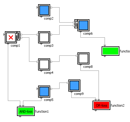
The following video shows some failure cases of the system in the figure shown in post [001].. Square boxes represent the components, rectangular ones the functions.

The blocks used here incorporate basically not more than such generic Boolean conditions. If a component provides an expected output – like “energized” – it is displayed in blue. If it provides no signal, it is white. And a nominally working function is green, while a failed function shows up in red. The analysis might remind you to FMEA – we’ll come back to that later.

The clue is, that each component may interactively set to “fails”, which means it fails to deliver its own service, locally, independent of its incoming supply. As the video shows, a simple simulation of such a network will immediately unveil, which functions will be affected by which component faults – indivudual ones or also combinations.

After having clarified these basic dependencies, we will introduce the concept of failure rates in post [003].

Architecture Product Development

[001] From Components to Functions

Orthogonality between functional view and componenet view in system engineeringWhen talking about aspects like functional safety, reliability or availability of technical systems, a crucial point is to clearly define, what we are talking about. Do we mean the components, the hardware, when we say “The system is unreliable.” or “We have 99.99% availability.” ?


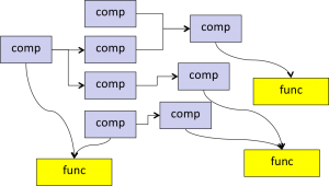
“The system” is indeed made up of a lot of individual components – blue in this figure. But at the end of the day we’d like to have functionality, performance, not hardware. All components are only used and needed to implement the desired functions – yellow in the figure.

So we usually have given requirements on the functional level, but need individual items – with their own properties – to make these functions work. No more, no less. The procedure of doing that by selecting, combining, assembling components appropriatelyis what we usually call “Engineering” – the art of Engineering.

In the next post we are going to show the two inverse views within system engineering and safety engineering.

General Product Development

[000] What is it about?

Training and education (cartoon)Here we intend to write in a sporadic manner about the development of the library.

We will talk about the motivation, ideas behind, requirements, some principal ideas, arithmetics, design issues and possible application scenarios. But also on general aspects of system engineering and safety engineering.

The more mature the library gets, we will probably show its capability to support in various RAMS analyses, FMEA and FMECA  generation, Fault Tree Analyses, diagnosis, support of safety standards and safety integrity levels (SIL) and the like.

And we will demonstrate some of these things in video clips.

So come back soon or subscribe to the mailing list. In post [001] we will start with clarification of the system engineering view on components and function.